
Method
BEAM combines the well established principles of focusing-electrode logging and frequency-domain induced polarisation (IP) measurements.
3D-finite elements calculated model of
BEAM-focused current and voltage ahead of the face
Low frequency electrical fields are generated by galvanic injected currents through an excavation specific focusing electrode configuration.
By adjusting the same voltage of same polarity simultaneously between the guard electrode A1 (+) and the return electrode B (-) and between the measuring electrode A0 (+) and the return electrode B (-), the measuring current is forced ahead of the face.
Thereby a distinct sensitivity zone for ground changes is established in a forefield distance of about 3 times the guard electrode A1 diameter, which is the tunnel diameter.
The obtained measuring parameters are the frequency-dependent resistivities R (f) and derived IP Percentage Frequency Effect PFE.
Thus, when the tunnel face is advancing towards a ground change, the continous electrical measurements are directly imaging and early warning the “coming” new geological situation.
Petrophysical Classification
BEAM is based on an advanced inhouse developed
processing, evaluation and visualisation
software which shows the measuring data and
distribution of percentage frequency effect
PFE and resistivity R for geological classification
and hydrogeological characterisation
The PFE characterizes the ability of the
ground to store electrical energy. Thus, it is
reciprocally correlated to the effective
porosity (permeability).
The Resistivity
provides additional information about the
fracture/cavity infillings (e.g. water, gas/air). Ground changes or obstacles are characterized
by typical combined PFE/Resistivity-anomalies, which define different geological/hydrogeological
ground situations (rock mass types
and water-inflow potential).
Based on correlation of geoelectrical PFE-data
and R-data to documented geological and
hydrogeological conditions at different tunnel
projects guided by BEAM surveys, a petrophysical
classification was developed for hard
rock and soft ground, each with 12
types.
Schematic presentation of focused-electrical field around a TBM heading
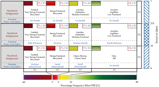
e.g. customized cross correlation and
classification matrix:
Rock mass types and water-inflow indication according to geophysical
parameters Induced Polaization (PFE) and Resistivity (R)
System
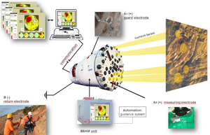
![]() The TBM based BEAM system allows a fully automatically and permanent driving accompanying exploration of ground conditions about 3 times the tunnel diameter.
The TBM based BEAM system allows a fully automatically and permanent driving accompanying exploration of ground conditions about 3 times the tunnel diameter.
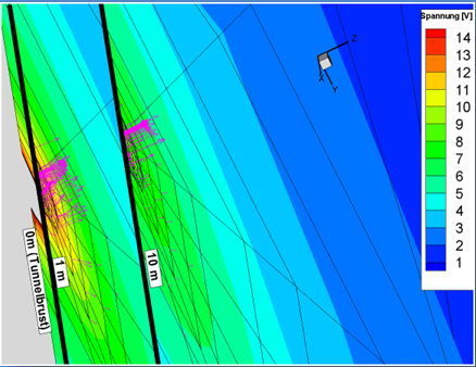
Visualisierung
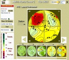
![]() e.g. lateral distribution view of PFE value: Indication of a cavity zone (red anomaly) within pyroclastics on the left top side ahead of the TBM.
e.g. lateral distribution view of PFE value: Indication of a cavity zone (red anomaly) within pyroclastics on the left top side ahead of the TBM.

References
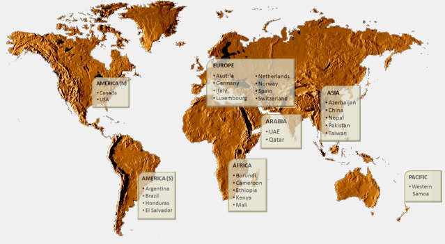
![]() Successful commercial application of BEAM® is realized since 2000 for more than 80 international tunnel projects, thereof 74 TBM projects with a total length of more than 300 km.
Successful commercial application of BEAM® is realized since 2000 for more than 80 international tunnel projects, thereof 74 TBM projects with a total length of more than 300 km.