
System
The TBM based BEAM system allows a permanent driving accompanying exploration of ground conditions about 3 times the tunnel diameter ahead of the face. Data acquisition and evaluation is performed automatically and prediction results are displayed in real time enabling fast on-site decisions.
An advantageous feature of the system is the utilization of excavation tools and safety constructional components as electrodes, which are automatically electrical coupled to the ground by the TBM itself.
Because of using voltages lower than 42V a continuous operation is possible without any danger for staff and machine.
Fully automatically and permanently measurements
of the ground conditions
ahead of the face
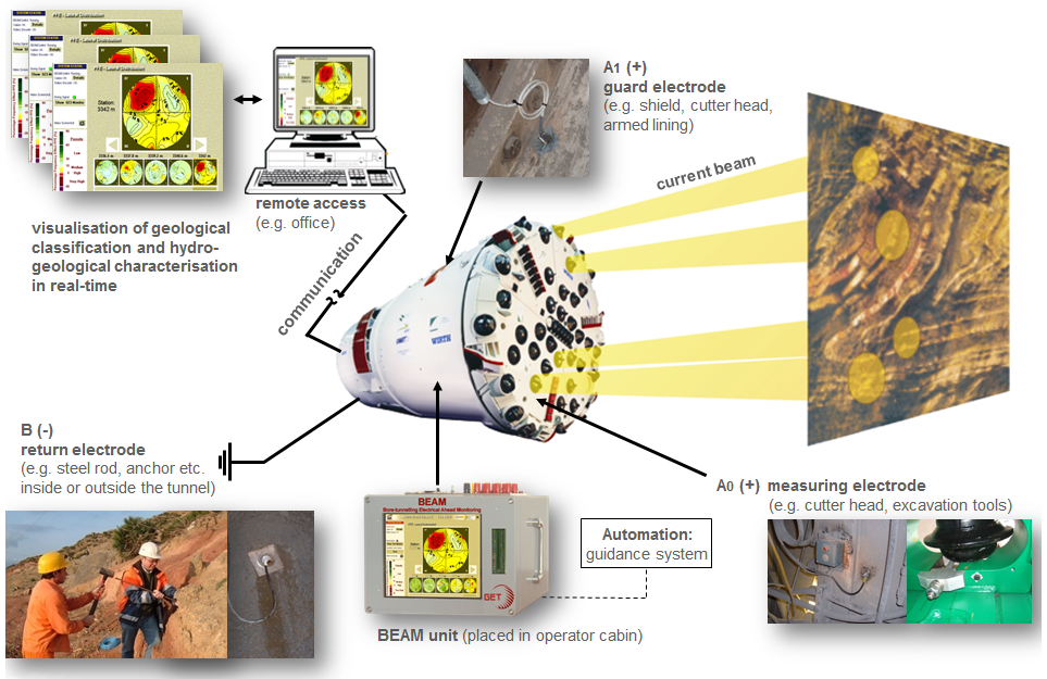
General System Layout
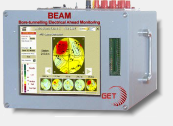
![]() BEAM unit: geoelectrical device placed in the TBM operator cabin as a stand- alone unit with integrated display or mounted in the display panel
BEAM unit: geoelectrical device placed in the TBM operator cabin as a stand- alone unit with integrated display or mounted in the display panel
![]() Measuring electrode(s) A0: whole cutterhead with all cutting tools or selected single cutters resp. rippers contacted to the face during boring rotation
Measuring electrode(s) A0: whole cutterhead with all cutting tools or selected single cutters resp. rippers contacted to the face during boring rotation
![]() Guard electrode A1: TBM shield or armed lining (including anchors)
Guard electrode A1: TBM shield or armed lining (including anchors)
![]() Return electrode B: fixed steel rod or anchor inside or outside tunnel in a large distance to the face
Return electrode B: fixed steel rod or anchor inside or outside tunnel in a large distance to the face
![]() Automation: connection of the BEAM unit via interface to the TBM guidance system and triggering of measurements by boring signal enables the fully automatically data acquisition with strokewise survey points
Automation: connection of the BEAM unit via interface to the TBM guidance system and triggering of measurements by boring signal enables the fully automatically data acquisition with strokewise survey points
![]() Communication: using internet access or a free telephone line for online maintenance purposes and transferring real-time prediction results from the BEAM unit in the operator cabin to site-office or to any other accredited computer outside tunnel
Communication: using internet access or a free telephone line for online maintenance purposes and transferring real-time prediction results from the BEAM unit in the operator cabin to site-office or to any other accredited computer outside tunnel
BEAM INTEGRAL System
BEAM-INTEGRAL is the basic system which uses the whole cutterhead/ cutting wheel as one large measuring electrode A0.
It can be easily and quickly installed in tunnelling projects currently under construction without any disturbance or stoppage of TBM excavation. Forefield prediction results are displayed one-dimensional and indicate investigation targets clear and timely.
The A0-INT measuring electrode is located as close as possible to the centre of the cutterhead, e.g. at or near by the rotary, fixed to the non-rotating parts. Surrounded by the A1 guard electric potential field the current through A0 contact is the measuring current focussed into the forefield.
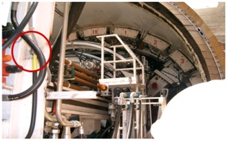
Connection of the measuring electrode AO (INTEGRAL mode) near cutter head.
BEAM SCAN System
BEAM-SCAN system uses additional selected A0 electrodes for an advanced lateral resolution ability, providing more detailed imaging of 2D and 3D targets. Additional installations and requirements like an electrical rotor, information about rotational position of cutterhead via rotary encoder and specially adapted insulated excavation tools (OEM) are necessary or using specific electrode plates along one arm of cutter head.
Several prepared excavation tools which must cover the TBM radius work as A0 measuring electrodes for the scan-mode.
Installation of the SCAN mode requires some additional preparatory work and should be equipped before start boring.
In general both systems have the same ability of detection in the forefield range. Significant differences between both systems are the 1D respectively 3D acquisition and visualisation of ground prediction results.
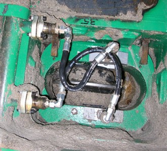
Insulated excavation tool as measuring electrode AO (SCAN mode) with cable/electrode protection
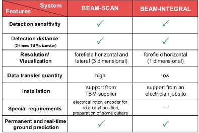
BEAM Systems in comparison
Applicability
BEAM is most favourable applied in modern mechanized TBM headings, because all key benefits become operative as there are:
![]() fully automated continous data acquisition and processing
fully automated continous data acquisition and processing
![]() real-time visualization of geophysical measuring results and geological/ hydrogeological interpretation
real-time visualization of geophysical measuring results and geological/ hydrogeological interpretation
![]() arbitrary data access from outside the tunnel
arbitrary data access from outside the tunnel
![]() data storage of all measuirng results for exchange as well as provision of a complete tunnel documentation
data storage of all measuirng results for exchange as well as provision of a complete tunnel documentation
It can be used in any geology like hard rock and soft ground and thus in EPB-, Slurry-, Gripper, Single or Double shielded TBM, independent from the manufacturer.
BEAM is sensing the induced Polarization and thus the effective porosity changes in the ground.
At the same time the measured resistivity is delivering the hydrogeological ground characterization.
BEAM works properly above or below the ground water table. In particular, if an EPB-TBM is boring below the ground water table, the BEAM evaluation software is able to differentiate between a water-bearing aquifer (high permeability zones like sand/ gravel) and an aquiclude (low permeability formations like clay) as well as water- or air-filled cavities, clay-, sand-, silt-filled anomalies or archeological remains.
Visualisation
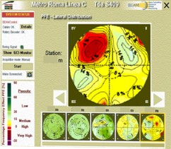
e.g. lateral distribution view of PFE values: Indication of a high porosity zone (red anomaly) within pyroclastics on the left top side ahead of the TBM.